What are Membrane Switches, and How do They Work?
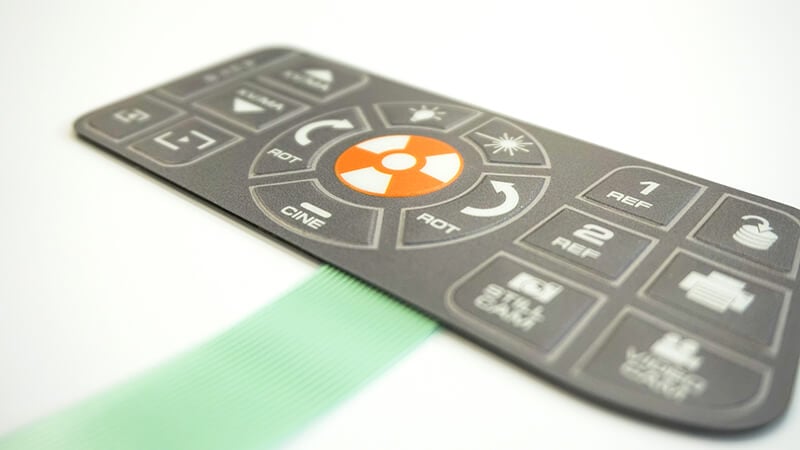
A membrane switch is an electrical control used to turn a circuit on and off that is often more cost-effective than mechanical switches. Membrane switches are used in various industries such as medical, industrial controls, safety, white goods and appliances, lighting, and so on. Membrane switches are slim-profile plastic keypads with buttons.
They are commonly used for applications where a quick response is needed but not when a closed circuit is intended, such as a light switch. They only work momentarily, whereas light switches are latching switches that complete a circuit until the switch is flipped back on.
What Goes into Designing a Membrane Switch?
When designing a membrane switch, there are many design elements to take into consideration. You can incorporate unique features depending on several different factors. Our team at Butler Technologies will work to customize each membrane switch based on your specific needs. We help you determine what features would work best for your application through a simple and painless process.
The Steps Involved
It is best to establish all of the details that will go into your switch design before taking your membrane switch into full-scale production. Each element is essential and will ultimately help ensure the membrane switch operates correctly based on your specifications and needs. Different features can be incorporated into your membrane switch design based on your specific needs.
1. Defining Product Requirements and Operating Environment
Before a membrane switch goes through engineering, you must address several different factors. Firstly, are you developing a new product design? Have you already created a product design that needs to be revised? Or do you already have an existing piece that will need to be reverse engineered? The development process will be different for each of these scenarios.
A membrane switch design for a healthcare application may be entirely different than a membrane switch design for a fire safety application. The operating environment for membrane switches is crucial to establish. This is primarily because of the unique features that may need to be incorporated, especially if you plan to use the design in a rather harsh environment.
You will need to address whether you will use the membrane switch in an indoor or outdoor scenario. If it is indoors, will it be exposed to any harsh chemicals? If so, you may want to make your membrane switch chemical resistant. If you plan to use the design primarily in an outdoor setting, will it be exposed to any harsh temperatures or humidity? You would need to make your design UV, heat, or even water resistant.
Determining the operating environment is essential, as certain features may need to be incorporated to ensure your switch’s full functionality and durability.Lastly, will the membrane switch require color matching? Color matching means you may have a branded color that you would like used for your product’s design.
2. Pricing and Production Location
There are a few different production options that will affect the overall pricing and lead time for parts. Knowing if your project is more time or budget-sensitive will help determine whether your switch is made in-house or offshore.
In most cases, in-house production will provide you with less lead time but may increase the overall piece price. If price is a more crucial factor, offshore production can provide a lower overall price with the tradeoff of longer lead times.
3. Quality Considerations/Approvals
Many membrane switch designs must be made to meet certain quality considerations and approvals. Below are many of the quality concerns our company can help with.
Ingress Protection: You can make membrane switches with a perimeter seal, similar to a picture frame. This helps prevent dust or water from getting inside the switch, causing damage to the electronic components.
International Traffic in Arms Regulations (ITAR): ITAR is a set of government regulations related to defense exports. Many manufacturers and exporters of defense articles related to technical data or defense services are required to register.
Preproduction Part Approval Process (PPAP): This is an industry-standard that ensures engineering design and product specification requirements are being met.
ISO-13485: This certification demonstrates our ability to provide medical devices or products related to medical devices that consistently meet customer and applicable regulatory requirements.
ISO-9001:2015 with Design: This is an international standard that specifies requirements for a quality management system (QMS).
RoHS: Being RoHS compliant is a directive on the restriction of using certain hazardous substances in electrical and electronic equipment.
If any of these quality considerations and approvals pertain to your switch’s design, you should also bring this up before going into development.
 4. Material Needed
In a quality membrane switch, choosing the right material is vital. The most common materials used in the overlay of your membrane switch are polyester, polycarbonate, or acrylic. Each has its unique benefits.
Polyester: Polyester overlays are the most frequently used, as they have good chemical resistance and can withstand higher temperatures. You would most likely use them in applications where the product may be exposed to harsh environments, climates, chemicals, or cleaning agents. They are also the most durable. For polyester material, the typical thicknesses range from 0.005″ to 0.010″.
Polycarbonate: Polycarbonate is a common material used when impact resistance or transparency are required. Polycarbonate material is known for how easy it is to laser cut, die-cut, screen-print, and texturize. However, if polycarbonate were needed to be chemical resistant, it would require hard coat protection to be applied as opposed to polyester, which can naturally withstand harsh chemicals. Polycarbonate can be exposed to a temperature of approximately 220 degrees Fahrenheit. If needed, another polycarbonate material, known as Fire Retardant Polycarbonate, can be used to help with temperature extremes the overlay may be exposed to. For polycarbonate material, the typical thicknesses range from 0.005″ to 0.030″.
Acrylic: Acrylic material is the least commonly used but has recently gained popularity because it is so lightweight and clear. If the main priority of the material is to diffuse or transmit light, then an acrylic material may be the best option. Acrylic material is strong, so it does not bend easily and can provide display durability and stiffness to your switch design.
For membrane switches, choosing the appropriate finish will help complete the look and feel of the final product. Membrane switches can have a matte, gloss, velvet, or brushed finish typically.
For membrane switches, most start with a clear color. However, choosing the appropriate finish is essential. Membrane switches can have a matte, gloss, velvet, or brushed finish typically.
5. Adhesive
Choosing a suitable adhesive is vital. Factors to consider when choosing your adhesive include application surface, service temperature, and other environmental considerations such as chemical exposure and humidity.
Option 1: 3M 200MP High-Performance Adhesives are typically the industry standard for attaching graphics and membrane switches to high surface energy plastics and other surfaces. They are excellent in chemical and humidity resistance and have an available thickness from .002″ to .005″. The thicker version is best suited when applied to a textured surface. For prolonged use, the service temperate should range from -31°F to +300°F, and for short periods it can last in temperatures of +400°F.
Option 2: 3M 300 High Strength Adhesives are great when applied to surfaces with low surface energy plastics or foam. They are excellent for applications requiring greater initial adhesion, especially to foam materials or low surface energy plastics. These come in thicknesses of .002″ to .005″. For prolonged use, they can operate in temperatures from 150°F – 225°F. For short periods of use, it can withstand a heat resistance of +250°F.
Option 3: 3M 300 LSE High Strength Adhesives are also a great option for low surface energy plastics, powder-coated metals, or lightly oiled surfaces. They are extremely chemical resistant and great for humidity resistance. They typically have an available thickness of .002″ to .005″. For long-term use, they work best in temperatures ranging from 40°F to +200°F, and for short-term use, they can withstand temperatures of +300°F.
Although these are the three most commonly used materials, there are many other adhesives available. You can learn more here about other adhesive options.
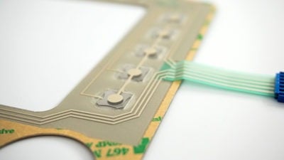
6. Circuit & Tail Design
The electrical layout of the circuitry found inside the membrane switch will dictate the overall build and composition of the switch. Firstly, you will need to determine how many buttons, otherwise known as contact points, are required. After establishing how many contact points are required, you can choose the type of pinout that would work best for the application. The two types of pinouts typically used are the Common Bus Pinout and the X-Y Matrix Pinout.
Typically, the contacts of the electrical design are rated to carry a maximum of 100mA for standard circuit traces (0.039″ width). The power rating for a closed-loop resistance should be below 1.0 watts, and in most cases, is less than 100 ohms.
Tail Design
The next step is designing the tail itself. How long does the tail need to be, and where do you want to position the tail on the switch? You should address these points during the design phase because it will impact the composition of the switch.
If the design is non-complex, a simple screen-printed silver circuit with a ribbon cable tail may be the most appropriate option. You may be encouraged to use etched copper flex over polyimide if the design is complex or if the ribbon cable will be bent or creased. Though this is a more costly option, it works well for circuits where trace traffic may be congested or if a double-sided circuit application is needed.
After the overall design has been established, you can choose how the circuitry will be physically connected to the PCB board. A solder tab is the simplest option, but sometimes a connector is required. Both latching and non-latching options are available. Latching connectors have a tab that engages with the mating housing or connector and improves retention where it may be exposed to shock or vibrations. In contrast, non-latching connectors do not have a locking tab. You can also design your ribbon cable to slide into a ZIF connector or board-mounted header (female or male pin with housing)
Determining what connector or tail termination is best for your membrane switch design is also critical. Several different connectors are ranging from ZIF, Nicomatic, and Berg to choose between.
In a connector, you must first establish the pitch or the distance between the pins of a connector. In other words, there are silver traces found at the end of the tail, and the pitch is the distance between those two traces.
ZIF is short for Zero Insertion Force Connector. A lever or slider that is moved with a ZIF socket will allow room for the tail to be inserted with very little force. When the lever or slider is moved back, it allows the contacts to close and grip the pins of the tail. Standard trace pitches are typically 1.27mm and 2.54mm.
Nicomatic is the manufacturer of the Crimflex housings that our team typically uses on tails when needed. Standard pitches for these housings are 1.27mm and 2.54mm. The housing is crimped onto the end of the tail using a tool specifically for that brand.
Berg is the manufacturer of the style connector we commonly use on tails when needed. The standard pitch for Berg connectors is 2.54mm.
7. ESD Shielding (Optional)
ESD is only required if the switch will be exposed to environments where there is a high risk of static charge being pushed into the buttons during function. If a static charge needs to be dissipated, there are a few options available. The first is a screen-printed grid pattern made up of conductive silver ink. It can be grounded to a trace on the interface panel, then ultimately rerouted to a ground plane on the product to help eliminate the electrostatic charge. The second option is to have fully conductive laminates, foils, and tapes inside the product. Although this is the more expensive option, it also has higher dissipative properties for environments where an electrostatic charge may be more prevalent.
8. Tactile vs. Nontactile Keys
There is only one thing to consider when determining whether you would like tactile or nontactile keys in your switch design. Do you want the keys to provide some sort of feedback that they have been pressed to the end-user? If the answer is yes, your design should include tactile keys to give tactile feedback. If the answer is no, your design would require nontactile keys, so no feedback is given off.
For tactile keys, you have the choice between metal domes or polydomes. Metal domes are simple, as they click to provide tactile feedback to the end-user. Polydomes are typically used in polycarbonates or polyesters and are formed at the button location to give a snap or tactile feedback. Polydomes are not
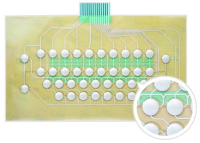
typically used as a common solution because they are the more expensive option.
When designing keys with metal domes, size and force can change the feedback the user experiences. The size of the keys will primarily be related to the choices made with the graphic design on the overlay. The dome force will be how much pressure you want the end-user to use to activate the button. Typically, metal domes have force options that range anywhere from 180-700 grams. However, 340-350 is the most common. Metal domes come in various shapes and sizes and are typically nickel or gold-plated, variant on the conductivity needed for the switch. Plated domes offer better conductivity and resistance to oxidation.
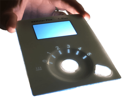 9. Backlighting (Optional)
Backlighting is also an option for membrane switches that may be used in darker environments. Typically, Light Guide Film (LGF) is used. To enhance the lighting effects, LGF distributes light evenly from side-firing and top-firing LEDs. LGF is considered to be rather sleek and efficient compared to alternative backlighting options, which is extremely important in a membrane switch design where the interface is to have a very low profile.
10. Forming/Embossing (Optional)
As discussed previously, if your control requires tactile feedback, you may consider polydomes over traditional metal domes. If this is the case, thermoforming is used to create raised, tactile buttons. Thermoforming provides greater design flexibility, but tooling costs will cause an increase in the overall price. Typically thermoforming is best for complex shapes, designs with multiple levels, or detailed logos.
Embossing keys provides another level of feedback for the user and can be helpful in applications where locating keys on the switch is important. This method involves using male and female magnesium dies to shape the key location. This method works for most applications, but there are typically height limitations that you must take into consideration.
When considering embossing, there are two popular options: Rim Embossed and Pillow Embossed. Rim embossed means that a raised edge is embossed around the perimeter of the button. Pillow embossed means the entire key is raised to sit over the metal dome.
11. Other Important Factors
After you have successfully gone through each of the above steps, your membrane switch design is basically complete. There are other things to consider, such as any selective textures you may desire for the overlay and the overall height requirements for the switch.
Designing your membrane switch can seem like a rather tricky task, but by working with our team at Butler Technologies, we can make the process easier. By following the steps above and working alongside one of our team’s experienced engineers, we can help you create the perfect membrane switch design for your specified application. For more information, or to get your next project started, reach out. Our team is ready to help!
 Meet the Author: Jaclyn King
Jaclyn was previously the marketing communications specialist on the BTI Team.