
A membrane switch appears to be a simple flat panel, but beneath the surface lies a complex assembly of flexible materials, printed electronics, and pressure-sensitive adhesives. For engineers, understanding this "stack-up" is critical to designing an interface that survives in the real world.
At Butler Technologies, Inc. (BTI), we don't just print circuits; we engineer high-reliability interfaces. Whether it is preventing silver migration in humid environments or designing IP67 seals for outdoor equipment, the difference between a functional switch and a failure often lies in the invisible details of the construction.
This guide takes you inside the stack-up, layer by layer.
The Anatomy of a Membrane Switch (The Stack-Up)
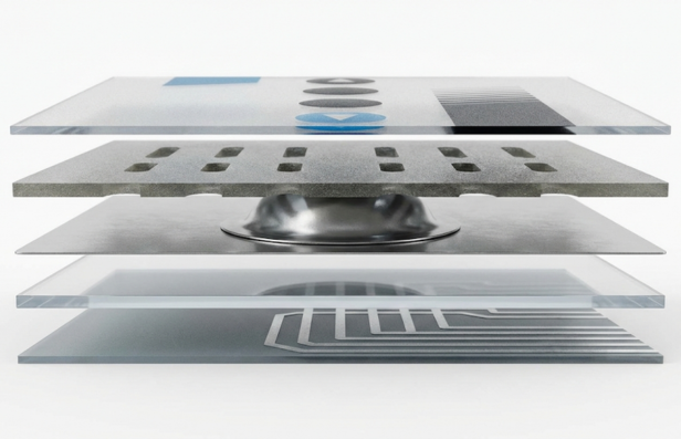
A standard tactile membrane switch is typically composed of six to nine distinct layers. Each layer serves a specific mechanical or electrical function.
Layer 1: The Graphic Overlay
This is the user-facing surface. It creates the visual identity of the product and serves as the first line of defense against the environment.
- Material Science: We predominantly recommend polyester (PET) for the overlay. Unlike polycarbonate (PC), which is prone to stress cracking after approximately 100,000 actuations, PET is semi-crystalline and can withstand over one million actuation cycles without fatigue failure.
- Surface Treatment: For medical or industrial applications, we apply selective textures—matte finishes to hide fingerprints on buttons and gloss finishes on display windows for optical clarity.
Layer 2: Overlay Adhesive
This layer bonds the graphic overlay to the top circuit or dome retainer.
- Venting: This adhesive layer is not a solid sheet; it must be channelled. When a button is pressed, air inside the switch needs to move. If the adhesive blocks the airflow, the button will feel hard to push or "sluggish" on return.
Layer 3: Dome Retainer / Top Circuit
- Tactile Switches: This layer is a thin polyester film used to hold metal domes in place, ensuring they don't shift during operation.
- Non-Tactile Switches: In switches without domes, this layer features a "shorting pad"—a conductive ink printed on the underside that bridges the circuit when pressed.
Layer 4: Spacer (The Air Gap)
The spacer is the most critical layer for preventing false actuation. It creates the gap between the top and bottom circuits.
- Thickness: Typically 0.005" to 0.007" thick. The thickness determines the actuation force and travel distance. If the spacer is too thin, the switch may be too sensitive (hair-trigger); if too thick, it requires excessive force to actuate.
Layer 5: Bottom Circuit (The Brain)
This is where the electrical signals are routed.
- Screen Printed Silver: The industry standard. Conductive silver ink is printed on heat-stabilized polyester. To prevent oxidation and wear from the metal dome, we overprint the contact pads with hard carbon ink.
- Copper Flex (FPC): For designs requiring high density (0.5mm pitch) or soldered components (LEDs, resistors), we use etched copper on Kapton (Polyimide). This is more robust than silver but comes at a higher tooling cost.
Layer 6: Rear Adhesive & Rigid Backer
The final adhesive layer bonds the switch to your product housing.
- Adhesive Selection: We typically use 3M 467MP for smooth metal housings and 3M 300LSE for low-surface-energy plastics (like powder-coated surfaces or polypropylene).
- Rigid Backer: For standalone panels, the switch is laminated to an Aluminum or FR4 backer to provide structural support.
 How It Works: The Mechanics of Actuation
Membrane switches are a "momentary normally-open" switch. Here is the step-by-step physics of a key press:
- Force Application: The user applies force to the graphic overlay.
- Dome Collapse: The pressure travels through the overlay to the metal dome. Once the force exceeds the dome's "trip force" (typically 340g), the dome snaps, inverting downwards.
- Circuit Closure: The center of the dome touches the fixed contact pads on the Bottom Circuit, bridging the gap between two traces. This completes the electrical loop.
- Venting: As the dome collapses, the air inside the cavity is displaced through the vent channels cut into the spacer layer. This air moves into the surrounding spacer area or out through a rear vent.
Release: When the user removes pressure, the metal dome uses its elastic memory to spring back, breaking the circuit and providing the tactile "click" sensation. Critical Engineering Challenges
At Butler Technologies, we solve specific failure modes that often go overlooked in basic designs.
1. Venting: Internal vs. External
A sealed switch is a pneumatic system. If air cannot escape, the switch won't work.
- Internal Venting: Air moves between keys. When Key A is pressed, air flows to Key B's cavity. This is preferred for IP67 sealed switches as it requires no holes to the outside world.
- External Venting: Air is vented out the back of the tail or through the connector. This allows for easier actuation but creates a path for moisture ingress if not carefully managed.
2. Silver Migration (The Short Circuit Risk)
In high-humidity environments, silver ions can migrate between traces, growing "dendrites" that cause short circuits.
- BTI Solution: We use Double-Sided Polymer Circuitry (D/SPC) or heavy carbon overprinting. By routing positive and negative traces on opposite sides of the film or capping silver with inert carbon, we eliminate the migration path.
3. Connection Reliability
The connection point (tail) is the most vulnerable part of the assembly.
- ZIF (Zero Insertion Force): Low cost, but relies on friction. Good for static applications.
- Nicomatic / Crimp Connectors: Metal teeth pierce the tail layers, creating a mechanical lock. This is the standard for high-vibration environments (industrial/automotive) as it resists pull-out forces.
Engineering FAQs
What is the stack-up of a membrane switch?
A typical stack-up includes six layers: 1) Graphic Overlay, 2) Overlay Adhesive, 3) Dome Retainer/Top Circuit, 4) Spacer (dielectric), 5) Bottom Circuit, and 6) Rear Adhesive. An optional rigid backer (Aluminum/FR4) may be added for support.
How does a tactile membrane switch work?
It works by deforming a metal dome or an embossed polymer dome. When pressed, the dome collapses, bridging two conductive traces on the bottom circuit layer. Upon release, the dome springs back, breaking the connection and providing tactile feedback.
Why use a metal dome instead of a polydome?
Metal domes (stainless steel) offer a crisper tactile feel, higher cycle life (>1 million), and better temperature stability compared to polydomes, which are formed from plastic and can lose their "snap" in high heat.
What prevents moisture from entering a membrane switch?
Ingress protection is achieved by a continuous "perimeter seal" of pressure-sensitive adhesive (like 3M 467MP). A "tail filler" (a small plastic shim) is inserted where the tail exits the switch to plug the gap in the adhesive, ensuring a full IP67 seal.
Do you have a complex interface challenge? From shielding against EMI to ensuring functionality in extreme cold, Butler Technologies engineers solutions that work where others fail.