
Membrane switches remain one of the most reliable and versatile interface technologies in modern electronic design. They combine thin construction, sealed surfaces, and long mechanical life in ways mechanical buttons simply can’t match. Today, they power medical equipment, industrial controls, diagnostic instruments, fitness systems, and countless consumer devices where durability and cleanliness matter.
As products get slimmer, smarter, and more rugged, membrane switches offer a controlled, customizable platform that integrates graphics, circuitry, tactile response, lighting, and sealing into one engineered assembly. Designing them correctly requires understanding how each layer works together, how circuits must be laid out, and how materials behave under stress, humidity, and repeated actuation.
This guide breaks down the best practices engineers use when designing high-performance membrane switch circuits.
What Is a Membrane Switch?
A membrane switch is a thin, flexible electrical switch that closes a circuit when pressed. Instead of mechanical contacts, it uses printed conductive traces on polymer films that deflect to create activation.
Engineers choose membrane switches because they offer:
- Sealed surfaces that block moisture and dust
- Excellent chemical and cleaning resistance
- Low profile, lightweight construction
- Long life expectancy, often exceeding one million actuations
- Fully customizable graphics and tactile feedback
Common examples include medical monitors, laboratory analyzers, industrial control panels, consumer appliances, diagnostic instruments, and wearables.
The Core Layers in a Membrane Switch
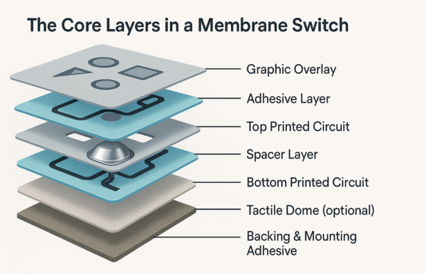
Membrane switches typically contain five to seven engineered layers working together as a single functional interface:
- Graphic Overlay – Printed overlay top surface with icons, branding, and indicators.
- Adhesive Layer – Bonds the overlay to the spacer or circuit layer.
- Top Printed Circuit – Conductive silver or carbon ink printed on PET.
- Spacer Layer – Maintains the air gap between circuits and defines switch travel.
- Bottom Printed Circuit – Static or dynamic contact surface.
- Tactile Dome (optional) – Metal or polydome actuator for tactile feedback.
- Backing & Mounting Adhesive – Attaches the switch to the enclosure or PCB.
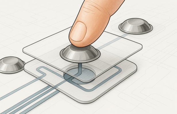
When a user presses a key, the top circuit flexes through the spacer opening and contacts the bottom circuit, completing the electrical path.
How to Design a High-Reliability Membrane Switch
Successful membrane switch design is rooted in material selection, stable circuit geometry, protective layering, and precise integration. Below are the core best practices.
1. Start With the Right Material Choices
Material decisions determine durability, chemical resistance, tactile feel, and long-term stability.
1 Graphic Overlay Materials
Choose based on environment, clarity, and durability:
- Polyester (PET) – Best for long life, chemical exposure, and continuous pressing.
- Polycarbonate (PC) – Excellent clarity for display windows; requires hardcoat for abrasion.
- Hardcoated Films – Ideal for medical or industrial use with harsh cleaners.
Additional overlay considerations:
- Use UV-stable inks for outdoor or high-light environments
- Select matte finishes to reduce glare
- Add textures or embossed keys to enhance targeting
For more insights on emerging trends and smart materials in graphic overlays, check out this blog on the future of graphic overlays.
2 Circuit Layer Materials
Common constructions include:
- Silver ink on PET – Industry standard for cost-efficient designs
- Carbon overprints – Add durability and reduce silver migration
- Copper on polyimide (flex circuits) – For high-density or high-flex applications
The circuit film must remain dimensionally stable under temperature, humidity, and pressure.
3 Spacer Layer
The spacer controls actuation force and prevents accidental electrical contact.
Best practices:
- Use uniform adhesive thickness
- Add vent channels between keys
- Keep openings aligned precisely with contact pads
4 Alignment and Registration
Precise alignment between overlay graphics, windows, domes, and circuits is essential.
- Aim for ±0.25 mm registration tolerance
- Use tooling pins or fiducial marks
- Oversize the overlay slightly to hide lower-layer edges
2. Follow Smart Circuit Layout Principles
Reliable circuitry requires proper spacing, geometry, and routing.
1 Trace Width and Spacing
Industry-accepted minimums:
- Trace width: ≥0.5 mm
- Trace spacing: ≥0.5–1.0 mm
Wider spacing reduces the risk of shorts and silver migration
2 Pad Design
Switch contact pads must be:
- Large enough for consistent actuation (around 3 mm or more)
- Centered beneath domes or touch areas
- Free from adhesive or debris that affects contact resistance
3 Keep-Out Zones
Avoid routing traces:
- Under tactile domes
- Near edges where environmental seals sit
- Under LEDs, windows, or perforations
4 Matrix Circuit Layout for Keypads
For designs with many keys:
- Use X-Y matrix scanning
- It reduces pin count and simplifies tail routing
- Example: a 4×4 keypad uses 8 traces instead of 16
5 Avoid Sharp Bends
Use:
- Smooth curves
- 45-degree angles instead of 90° corners
Sharp bends create stress points in conductive ink.
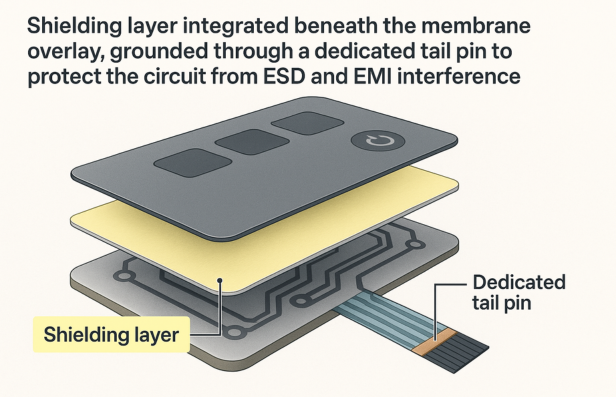
3. Integrate Proper Shielding and Grounding
Electrostatic discharge (ESD) and electromagnetic interference (EMI) are common threats.
Best shielding practices:
- Add a printed silver/carbon shield layer beneath the overlay
- Use aluminum or copper foil if high EMI protection is needed
- Use ITO when transparent shielding is required
- Always connect shields to ground through a dedicated tail pin
An ungrounded shield can worsen EMI rather than prevent it.
4. Engineer Tactile Feedback Correctly
Tactile performance defines user experience.
1 Metal Domes
Metal domes provide crisp, repeatable feedback.
Use best practices like:
- Dome sizes: 5–20 mm
- Actuation force: ~180–700 grams (common sweet spot: ~340 g)
- Gold plating for corrosion-prone environments
- Dome retainers with slightly oversized cutouts
- Venting channels for a consistent dome snap
2 Polydomes
Polydomes formed in the overlay offer:
- Softer tactile feel
- Metal-free construction
- More complex tooling requirements
3 Overlay Embossing
Embossing helps target keys by touch:
- Rim emboss: raised perimeter ring
- Pillow emboss: raised full key surface
Emboss height and spacing must meet material limits.
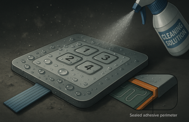
5. Protect Against Environmental Stress
Membrane switches excel in harsh conditions when properly designed.
1 Moisture and Dust Protection
To achieve IP65 or IP67 ratings:
- Use continuous adhesive perimeter seals
- Keep circuitry fully inside the sealed border
- Seal windows with bonded clear films
2 Temperature and Humidity
Prevent circuit drift and premature failure:
- Use heat-stabilized PET
- Select adhesives rated for expected temperatures
- Add carbon overprints to reduce silver migration
3 Chemical and Abrasion Resistance
For medical and industrial applications:
- Use hard-coated PET or PC
- Select inks resistant to cleaners and solvents
- Choose matte textures to mask scratches
4 Mechanical Strength
For large panels or frequent high-force presses:
- Add an aluminum or FR4 backer
- Ensure full-surface bonding to avoid creasing
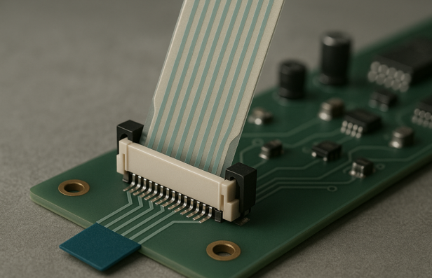
6. Design the Connector Tail for Reliability
The tail connects the membrane switch to the PCB and is a common failure point.
1 Tail Positioning
Place the tail so it:
- Exits cleanly with minimal bending
- Has a straight path to the PCB connector
- Avoids being routed under domes or high-pressure areas
2 Tail Geometry
Follow these guidelines:
- Maintain 2.5 mm clearance between traces and tail edges
- Use stiffeners to achieve ZIF connector thickness
- Use standard pitches (1.27 mm or 2.54 mm) for compatibility
3 Strain Relief
Add reinforcements or enclosure channels to:
- Prevent pulling
- Avoid sharp bends
- Reduce fatigue at the tail root
7. Test, Validate, and Verify
Before production, run comprehensive testing:
- Electrical testing – continuity, resistance, contact stability
- Mechanical testing – dome cycle life, emboss durability
- Environmental cycling – temperature, humidity, vibration
- Chemical exposure – cleaning agents and disinfectants
- ESD/EMI testing – compliance checks based on end-use industry
Testing ensures long-term reliability and validates material selection.
Summary
Membrane switch design combines materials engineering, circuit optimization, tactile mechanics, and environmental protection. With proper layer structure, stable circuit layout, grounded shielding, well-engineered tactile responses, and robust connector design, membrane switches deliver long life and consistent performance in demanding applications.
For high-performance, U.S.-manufactured membrane switches, Butler Technologies is one of the best brands that offers end-to-end engineering, prototyping, and production to ensure each switch performs reliably from the first press to the millionth.